Installing the odm-ea1 OLED display module
For Elektron Analog Four, Heat, Keys and Rytm (Mk1). Write-up and photos by Sip (Analog Keys), from the Elektronauts thread, with notes from xrd.lv and other installers there. Thank you!
Video
infekted's video tutorial shows the whole job, with tool suggestions:
Before you start
- Skill: this means desoldering a 20-pin header and two single pins, and soldering the new module on. If you are new to soldering, practise first, or ask a repair shop (several owners in the thread did; one paid about $100).
- Time: 1.5–4 hours, most of it disassembly (Analog Keys is the hardest to open).
- Tools: T10 and T9 Torx (Keys), soldering iron with a small tip, flux, solder wick, and a desoldering tool: a heated desoldering pump (Yihua 929D-V, about 15–25 €) makes it easy; a spring solder sucker with a silicone tip works too (on a hard tip, slide on a short piece of silicone tube). Kapton or painter's tape, isopropyl alcohol.
- Protect the plastic: cover nearby plastic (spacers, encoder shafts) with Kapton tape; the iron melts it easily.
- Spacers: do not use the spacers that came in the kit. Keep Elektron's original white spacers: the kit's are a different size on some units and push the screen protector out (seen on two Rytms).
1. Disassembly (Analog Keys)
For Analog Four: 6 faceplate Allen screws, detach 2 cables, then 8 hex screws to take the top board off the faceplate. Rytm and Heat are similar; only Keys needs the steps below.
Pull off the 13 knob caps (Master Volume, Level, the ten A–J encoders, the big Sound Selection knob). Lay the Keys upside down on something soft, keys facing you, minding the joystick. The bottom has 28 T10 Torx screws: red ones hold the back of the case, blue ones the keyboard.
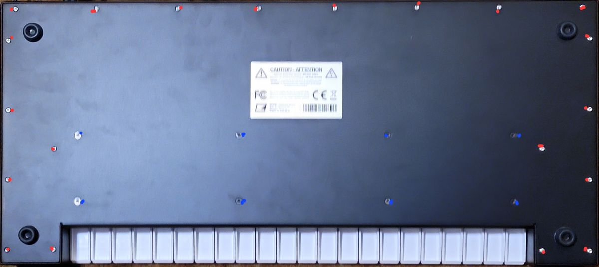
Lift the back slowly: a circuit board stays attached to it. Lift from the front and slide the panel slightly left so the board clears the metal tabs on the right. Three cables have little slack; disconnect the power connector (two white wires) and two 10-pin connectors, noting which way each faces.
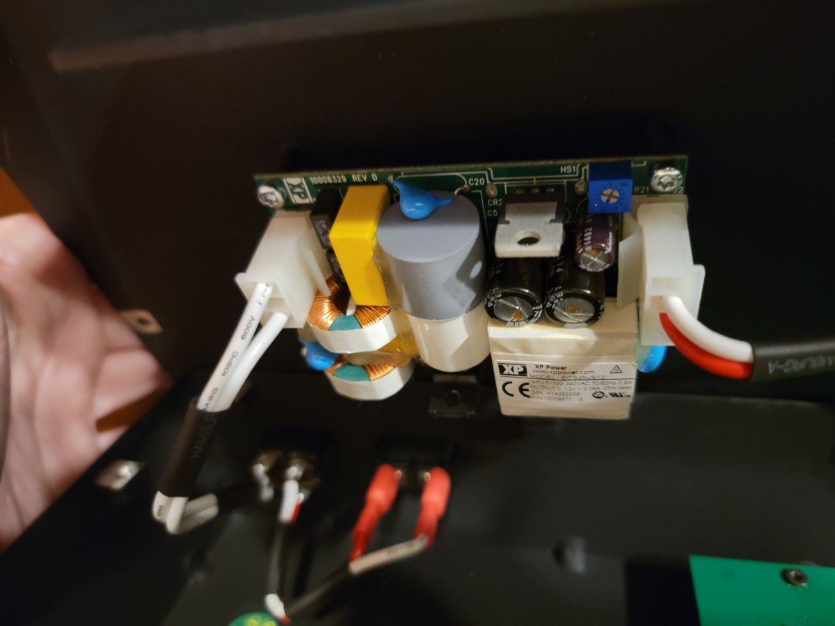
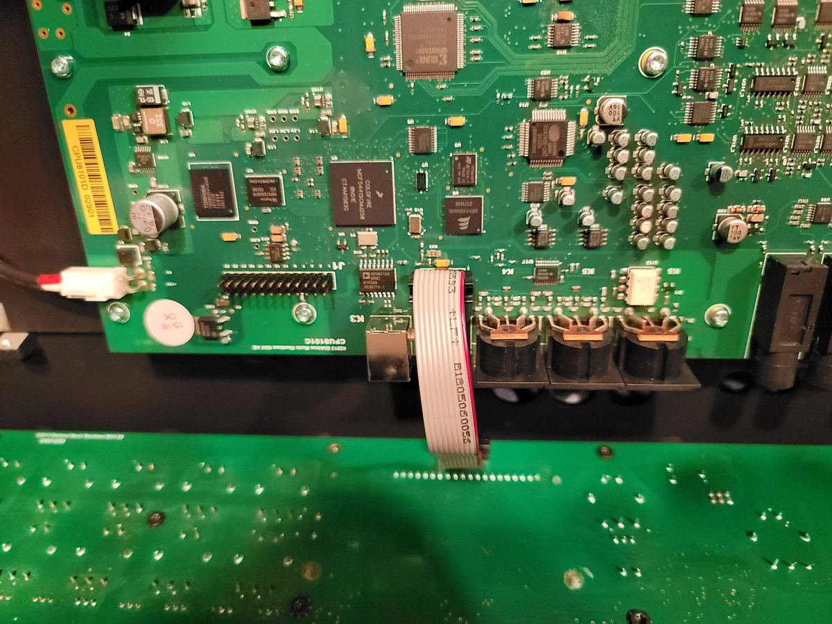
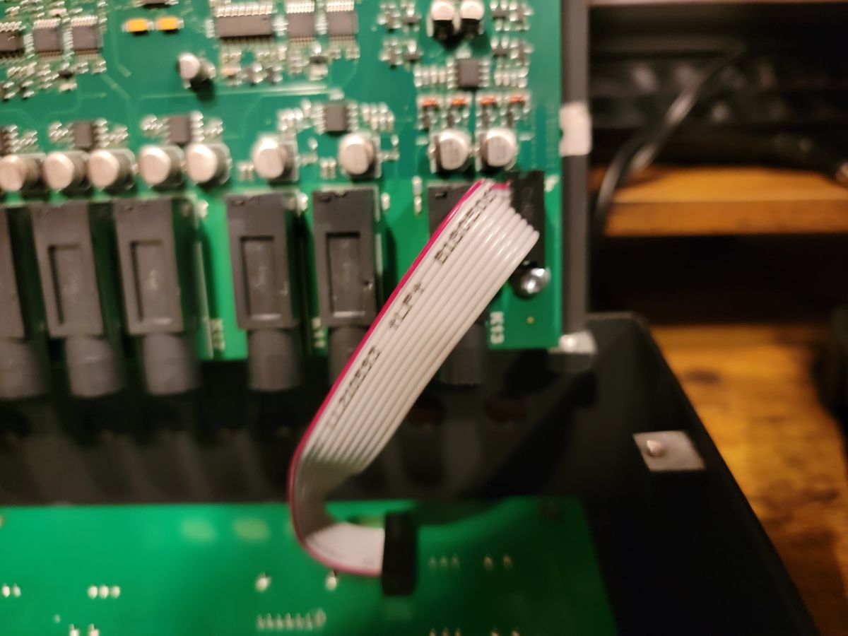
Disconnect the keybed from the front panel board: a blue 4-pin and a red 20-pin connector. Then remove the keybed.
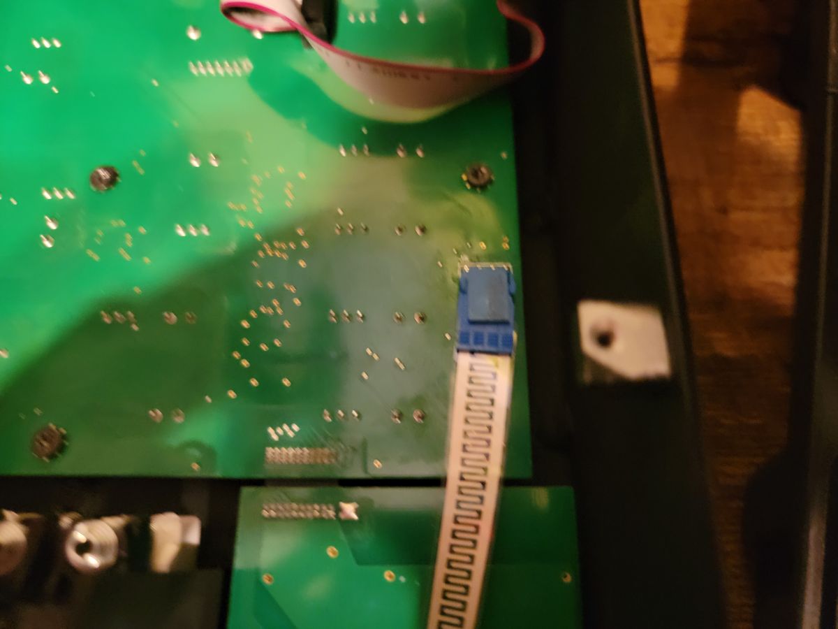
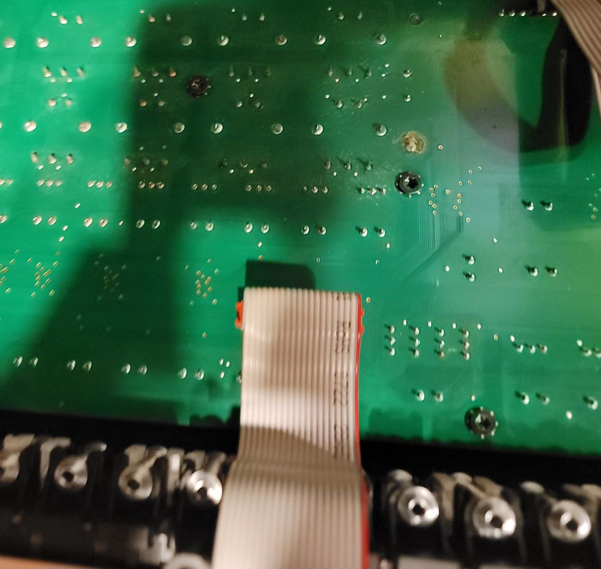
Disconnect the 40-pin ribbon to the key LEDs (bottom left; snug, almost no slack; easiest while the board is still screwed in).
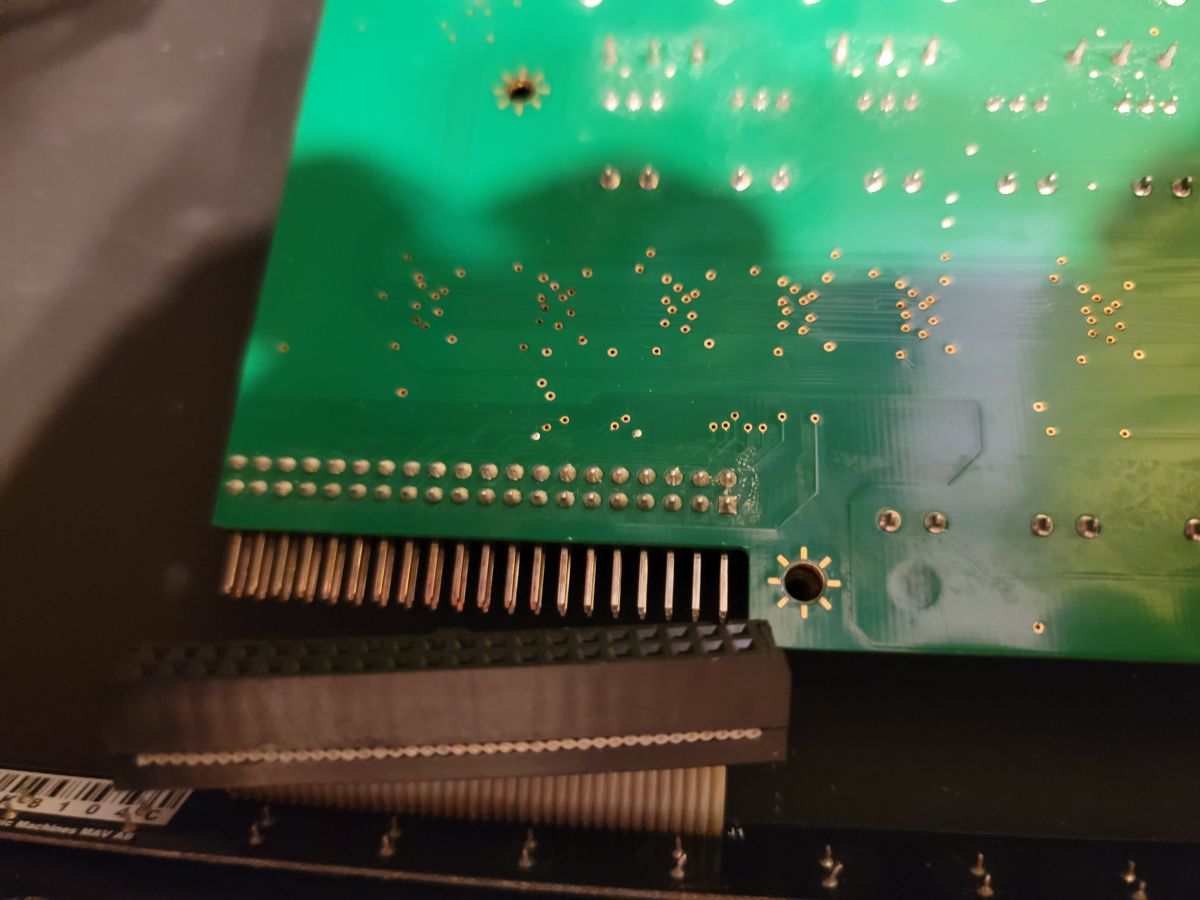
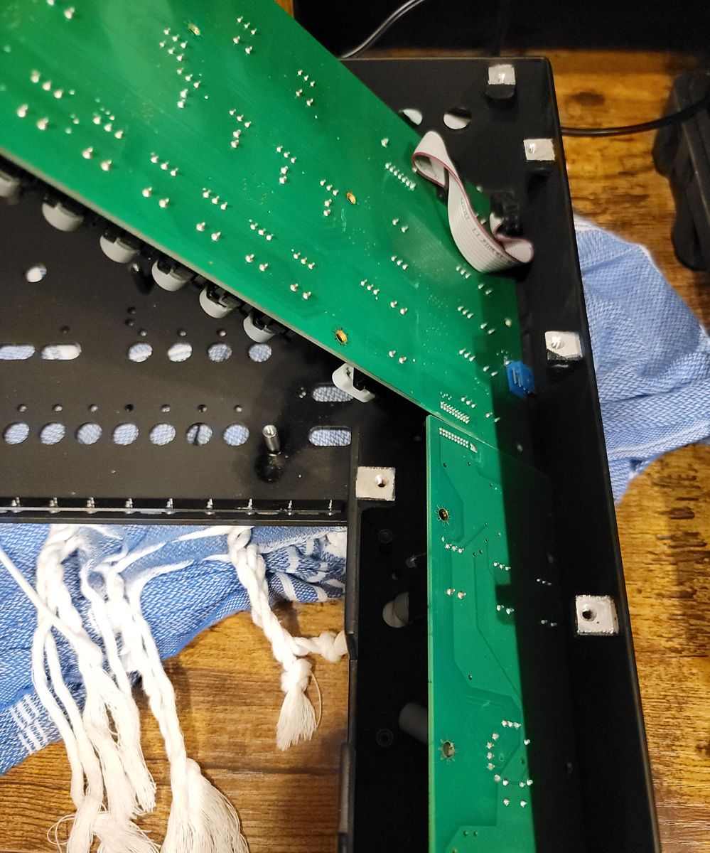
Remove the T9 screws holding the two boards to the front panel. Keep the joystick board connected to the large board; lift the left side of the large board while supporting the small one, tilt them up to clear the screw tabs, and take both out together. Then separate them.
2. Removing the old LCD
Desolder the 20 pins (blue line) and the 2 single pins (blue dots). The red arrow marks the trim pot used later for brightness. (The alternative, cutting the pins and replacing the headers with the ones in the kit, is less work but riskier for the board.)
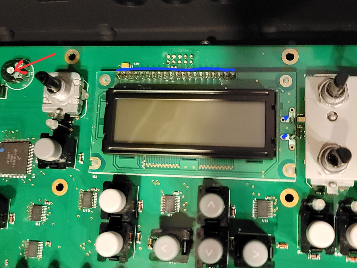
- Flux every joint. Add a little fresh solder to joints that won't clear: it seals the pump nozzle against the pad.
- Heated pump: let it heat up (5 min), put the nozzle fully over the pin, flat on the pad, wait about 2 s, release. One pin at a time; a second pass with fresh flux, extra time on the two side pins. Eject solder into a heat-safe dish; let the pump cool if it runs hot.
- Some installers desolder from the bottom side of the board, and only the two side pins from above.
- Wicking first, as Sip did, is optional; it can even make pumping harder.
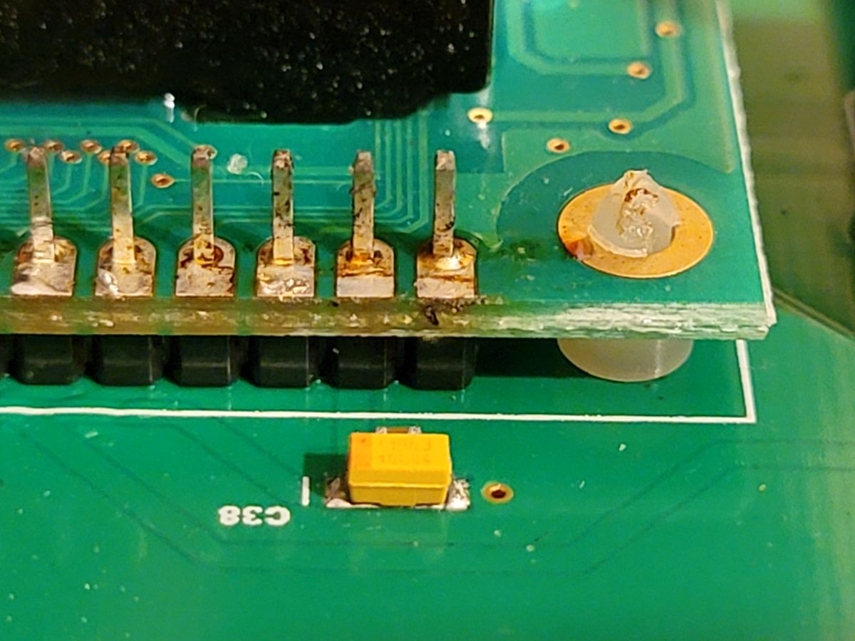
When all holes are clear, a firm tug lifts the LCD board off the pins. If it won't move, solder remains in a hole: add fresh solder and pump again. The bottom two spacers are glued from the back of the main board and stay there; the top two come off with the LCD. Move Elektron's spacers to the new module (squeeze the top of a spacer with pliers to free it). Clean the area with isopropyl alcohol.
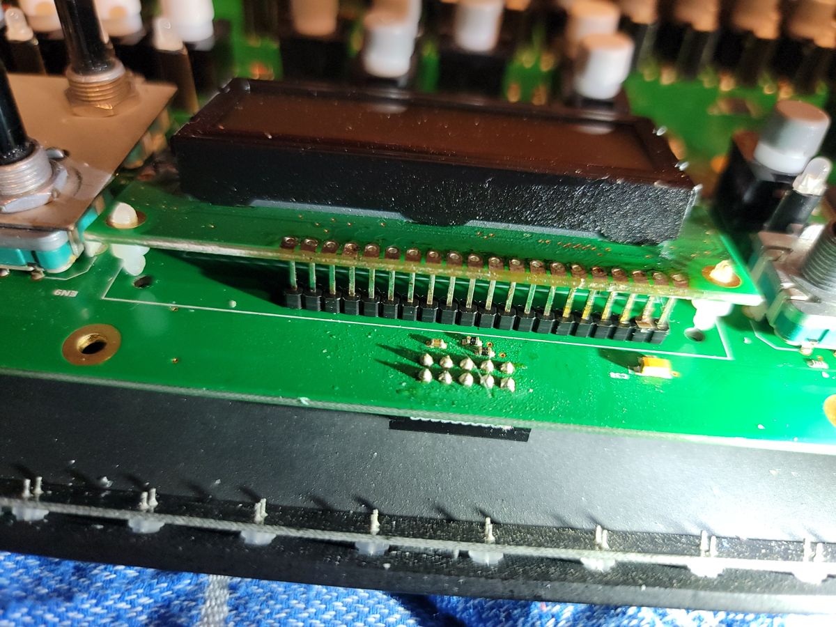
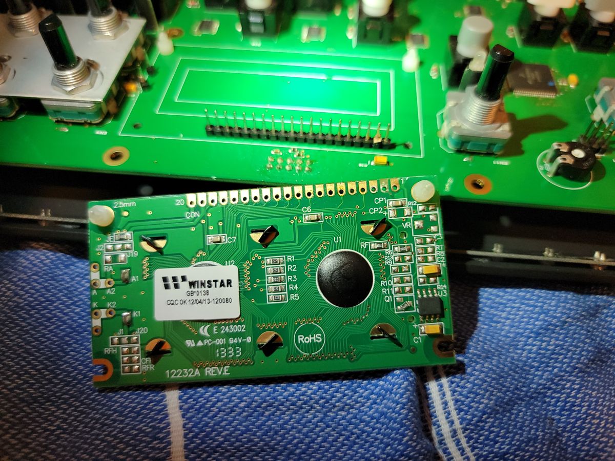
3. Soldering the new module
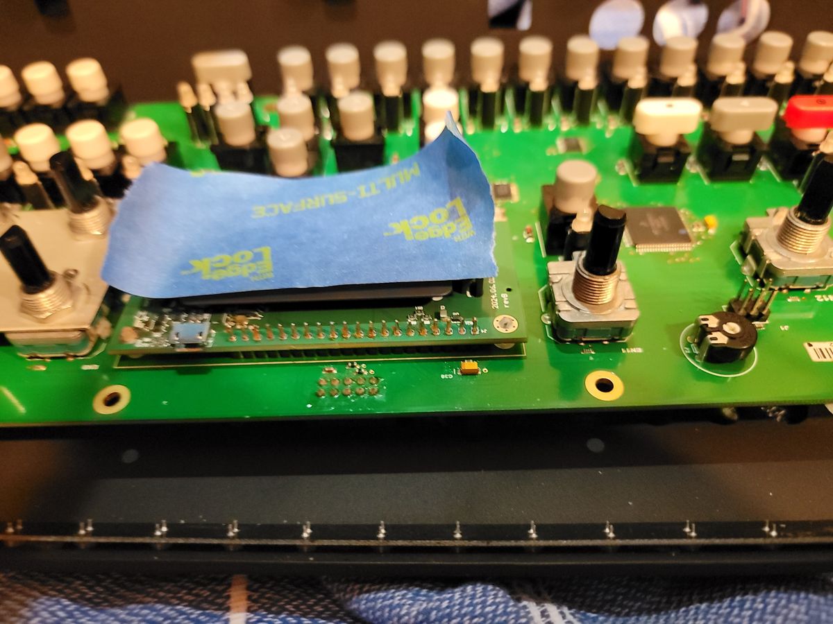
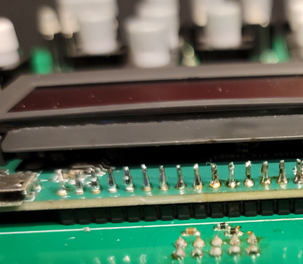
Tape over the OLED's face. Straighten any bent pin, slide the module onto the pins and solder all 22. A small tip helps; the ground pin is the awkward one to reach.
4. Test and brightness
On Four, Heat and Rytm, simply reconnect the board (a piece of cardboard between the boards keeps them apart) and adjust brightness on the device. On Keys, testing on USB power is easier: the module shows test text with DIP switch 6 on. To reach the DIP switches, push the long black clip at the top of the bracket toward the board and slide the screen out.
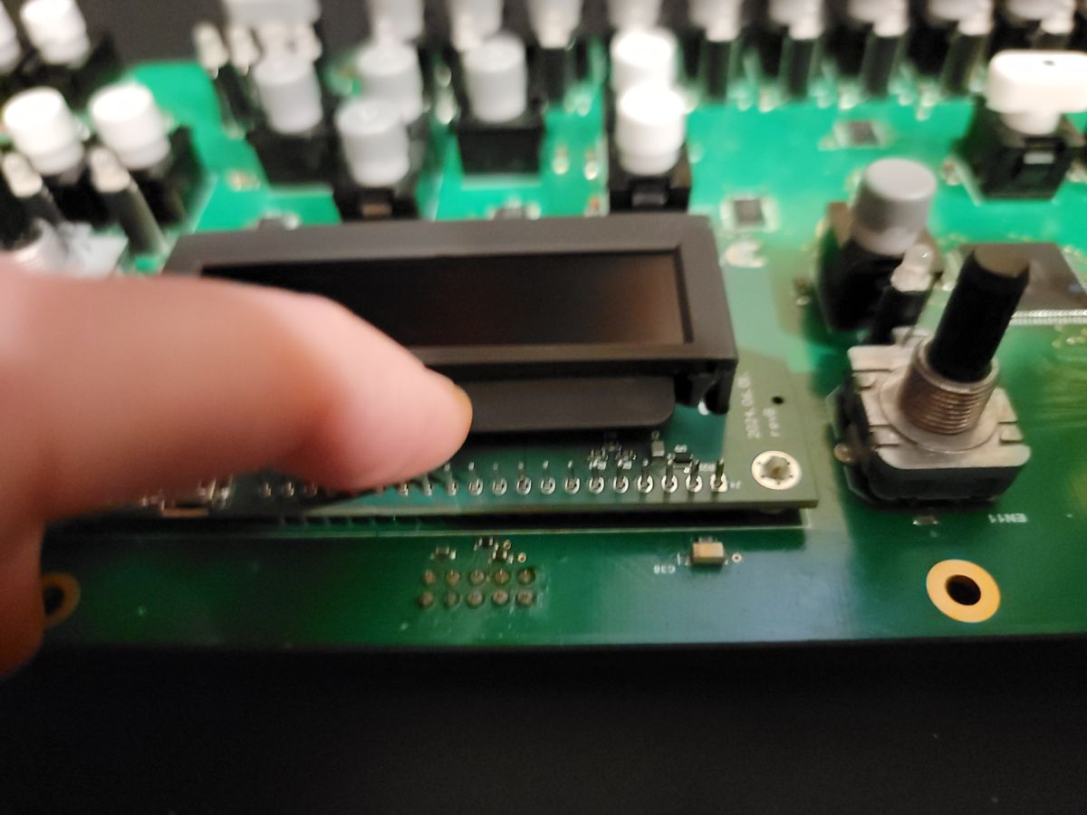
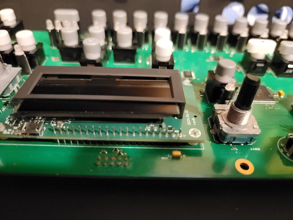
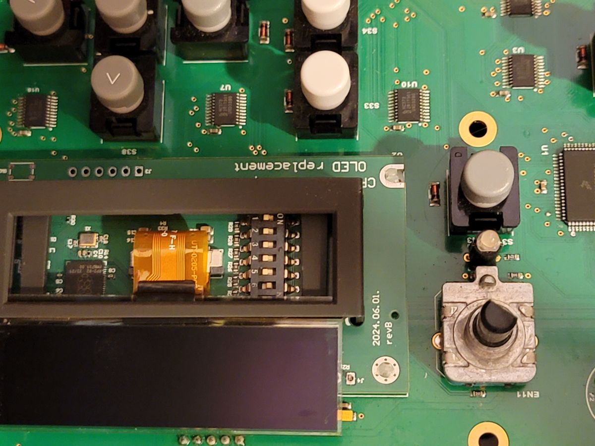
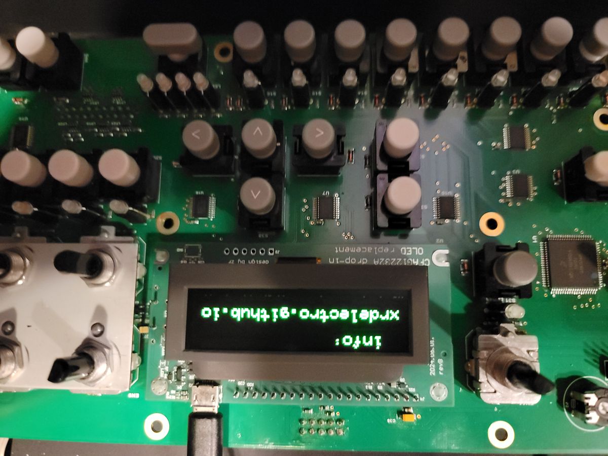
Adjust brightness with the trim pot (red arrow in the earlier photo) once the module is soldered. Then switch DIP 6 back off: the test switches 4–7 must all be off in normal use (DIP 7 on, for example, makes the screen look stuck). DIP 1–3 are settings (inverted display, fixed brightness levels); see the DIP switch page.
5. Reassembly
Reverse the steps. Fit the keyboard screws first. Screws only snug. Put in a few board screws, reconnect everything and test before fitting the rest: dust inside the screen window is easy to clean now and not later.
Troubleshooting
More in DIP switches and troubleshooting.
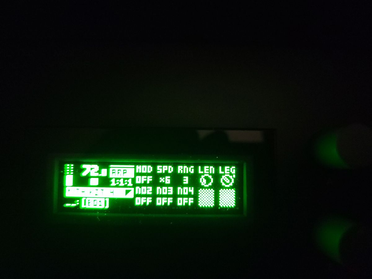
- Screen protector pushed out: the kit's spacers were used; fit Elektron's originals (or small bolts and nuts at the bottom).
- Strange or frozen screen: check that DIP switches 4–7 are off (unlatch the bracket: 4 snap hooks, press the top pair toward each other first).
- Vertical halo stripes, bottom-row leakage: fixed in firmware v1.0.5 (revC boards on). Write to e-mail with a photo of the serial number (left side of the bracket, below the code).